A pier and beam foundation carries the floor on isolated piers or posts that support girders, with joists spanning between the girders and the perimeter foundation. Under the 2021 IRC, masonry piers under floor girders must be at least 12 inches in nominal dimension (Section R404.1.9.2) and bear on footings sized by Section R403.1.1.
A pier and beam foundation (also called a post and pier foundation, or a pier and beam house when it carries a whole dwelling) lifts the floor above the soil on a grid of piers. A pier is a short column of masonry or concrete, and a post is a wood or steel column set on top of one. The 2021 International Residential Code (IRC) covers them in Sections R403, R404.1.9, R407 and R606. The adopted code edition and local amendments govern, and engineered or manufactured products follow the manufacturer's instructions.
Key facts
- Under 2021 IRC Section R403.1.1, footings under piers and columns are sized from the tributary load and the allowable soil pressure in Table R401.4.1.
- Under 2021 IRC Section R404.1.9.2, a masonry pier under a girder for an interior bearing wall has a minimum nominal dimension of 12 inches and a maximum height of 10 feet from top of footing to bottom of girder or sill plate.
- Under 2021 IRC Section R404.1.9.2, a masonry pier under a girder for an exterior bearing wall has the same 12-inch minimum but a maximum height of 4 feet.
- Under 2021 IRC Section R404.1.9.1, a hollow masonry pier is capped with 4 inches of solid masonry or concrete, a cap block, or grout or concrete in the top course.
- Under 2021 IRC Section R502.6, a girder end needs at least 1-1/2 inches of bearing on wood or metal and at least 3 inches on masonry or concrete.
- Under 2021 IRC Section R407.3, a wood column is not less than 4 inches by 4 inches nominal and must be restrained against lateral movement at the bottom.
What is a pier and beam foundation?
A pier and beam foundation is a raised floor system where the loads travel from joists to girders to piers to footings to soil, instead of through a continuous wall.
Joists span between girder lines and the perimeter, with spans from the floor joist span table. Girders span from pier to pier, so pier spacing is the girder span, and each pier sits on its own footing.
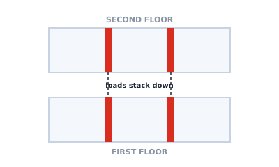 Load path from the floor framing down through the girder and pier into the footing
Section R403.1 says all exterior walls are supported on continuous footings (masonry, concrete or crushed stone), wood foundations, or other approved structural systems. So the outside edge is usually a stem wall on a continuous footing, and isolated piers carry the interior girder lines. A pier-only perimeter is an engineered or approved system, so ask your building department first.
How does a pier and beam foundation differ from a stem wall or slab?
A stem wall puts a continuous wall under the floor edge, a pier and beam system adds isolated supports inside it, and a slab skips the raised floor.
Comparison of foundation types for a light-frame house, with the 2021 IRC sections that govern each.
| Pier and beam | Stem wall with crawl space | Slab on ground | |
|---|---|---|---|
| Floor | Wood joists on girders | Wood joists bearing on the walls | Concrete at grade |
| Main supports | Isolated piers or posts, plus the perimeter | Continuous wall on continuous footing | Thickened slab edge |
| Governing sections | R403.1, R404.1.9, R407 | R403.1, R404.1 | R403.1.3.3 |
| Under-floor access | Required (R408.4) | Required (R408.4) | Not applicable |
What size and depth should a pier footing be?
Pier footing size comes from the load the pier carries and the soil bearing value, not from a fixed number, and exterior footings must be at least 12 inches below undisturbed ground.
Section R403.1.1 bases the size of footings under piers and columns on the tributary load (the share of floor carried by that pier) and the allowable soil pressure in Table R401.4.1. The general footing minimum in that section is 12 inches wide and 6 inches deep.
Section R403.1.4 puts exterior footings not less than 12 inches below undisturbed ground, and Section R403.1.4.1 requires piers and other permanent supports to be protected from frost, for example by extending below the frost line in Table R301.2. Section R403.1.3.6 permits isolated plain concrete footings under columns or pedestals in detached one- and two-family dwellings of three stories or less with stud bearing walls.
What are the rules for a concrete or masonry pier?
A masonry pier has height, thickness and cap limits in Section R404.1.9 and Section R606.7, and the girder rules depend on whether the pier carries an interior or exterior bearing line.
2021 IRC Sections R404.1.9, R404.1.9.1, R404.1.9.2 and R606.7: isolated masonry pier limits.
| Item | 2021 IRC rule |
|---|---|
| Hollow pier, minimum nominal thickness | 8 inches |
| Hollow pier, maximum nominal height | 4 times the nominal thickness |
| Hollow pier, maximum nominal length | 3 times the nominal thickness |
| Hollow units solidly filled with concrete or grout, maximum nominal height | 10 times the nominal thickness |
| Pier cap on hollow pier | 4 inches of solid masonry or concrete, a cap block, or top course cavities filled with concrete or grout |
| Pier under girder for interior bearing wall | At least 12 inches nominal, up to 10 feet high |
| Pier under girder for exterior bearing wall | At least 12 inches nominal, up to 4 feet high |
| Footing under an isolated masonry pier | Sized under Section R403.1.1 |
Section R606.7 adds that hollow units used for isolated piers under beams and girders are filled solidly with grout or Type M or S mortar, unless the pier is unfilled and no taller than four times its least dimension.
Piers supporting braced wall panels, piers in Seismic Design Categories D0, D1 and D2, and piers in flood hazard areas leave the prescriptive route (Sections R404.1.9.3 to R404.1.9.5).
How do girders, joists and the sill sit on a pier?
The girder sits on top of the pier, the joists sit on or hang from the girder, and the sill plate anchors the perimeter to the foundation.
Girders on piers. Section R404.1.9.2 permits masonry piers under wood girders that are sized to Tables R602.7(1) and R602.7(2). Girders and sill plates are anchored to the pier or footing under Section R403.1.6 or Figure R404.1.5.3. Girder sizes and spans are in those two tables, covered in the header and girder size chart.
Bearing. Section R502.6 requires at least 1-1/2 inches of bearing on wood or metal and at least 3 inches on masonry or concrete, unless approved joist hangers are used. Bearing on masonry or concrete is direct, or through a sill plate at least 2 inches nominal thick with a minimum nominal bearing area of 48 square inches.
Joists on girders. Joists bear on top of the girder or hang from its side in hangers, so the girder line sets the clear span. Rim joists close the ends, and blocking and bridging holds the joists upright at supports.
Sill at the perimeter. The sill plate is anchored with minimum 1/2-inch-diameter bolts at not more than 6 feet on center, embedded at least 7 inches into concrete or grouted masonry cells (Section R403.1.6).
When do you use a post instead of a masonry pier?
A post on a pier is used where the girder needs a narrow support, and the post must meet the column rules in Section R407.
Section R407.3 gives a wood column a minimum nominal size of 4 inches by 4 inches and a steel column a minimum of 3-inch-diameter Schedule 40 pipe to ASTM A53/A53M Grade B or an approved equivalent. Columns are restrained against lateral displacement at the bottom end, with a limited exception for short columns in Seismic Design Categories A, B and C. Wood columns follow the decay rules in Section R317 (Section R407.1).
What clearances does wood need above the ground?
Wood in a crawl space needs treated or naturally durable material where it sits close to bare soil, and the distances depend on the member.
2021 IRC Section R317.1 (items 1, 2 and 4): decay protection distances for wood in a crawl space.
| Member | Location | Treated or naturally durable wood where |
|---|---|---|
| Joists, or bottom of wood structural floor | Crawl space or unexcavated area within the foundation | Closer than 18 inches to exposed ground |
| Girders | Same | Closer than 12 inches to exposed ground |
| Columns | Same | Closer than 8 inches to exposed ground |
| Wood framing, including columns | Resting directly on concrete or masonry exterior foundation walls | Less than 8 inches from exposed ground |
| Ends of wood girders entering exterior masonry or concrete walls | At the wall | Clearances less than 1/2 inch on tops, sides and ends |
Field-cut ends and drilled holes in treated wood are re-treated under Section R317.1.1.
What about access, debris and ventilation under the floor?
Access to the whole under-floor space is required, and the ground must be cleared of vegetation, organic material and wood forms.
Section R408.4 requires access to all under-floor spaces: a floor opening not smaller than 18 inches by 24 inches, or a perimeter wall opening not less than 16 inches by 24 inches. Section R408.5 requires the under-floor grade to be cleaned of vegetation and organic material, and wood forms and construction materials to be removed before the building is occupied.
Ventilation rules (Sections R408.1 to R408.3) are amended in some jurisdictions, so check your adopted code.
How does a pier and beam foundation show on a framing plan?
Girder lines appear as beams with a size callout and a pier or post at each support. See load-bearing walls in a floor framing plan and the floor framing plan guide.
Summary
A pier and beam foundation carries the floor on girders that bear on piers or posts, each on its own footing. Under the 2021 IRC, interior-line masonry piers are at least 12 inches nominal and up to 10 feet high, exterior-line piers up to 4 feet (Section R404.1.9.2), footings are sized from tributary load and soil pressure (Section R403.1.1), and girder ends need 3 inches of bearing on masonry or concrete (Section R502.6). Seismic categories, braced wall panels and flood zones move the design to an engineer.
Framing Plan draws joist layouts, beams and openings and exports PNG, PDF and DXF. It does not check foundations, pier sizes or any other code requirement: the editor works in millimeters and its sample profile uses demo span figures and metric member sizes, so treat its output as a preliminary drawing aid. To lay out the joists and girders that sit on your piers, open the framing studio.