A framing plan is a top-down structural drawing for one floor or roof level. It shows the repeating members and which way they run, their on-center spacing, the beams and bearing walls carrying them, the openings framed through them, and the callouts tying each item to a schedule or detail. A building normally needs a separate plan for each level, because the framing and the support conditions differ level by level.
On a floor framing plan, the core of the drawing is often a single callout such as 2x10 JOISTS @ 16" O.C. next to a span arrow: the member, the spacing, and the direction the joists run.
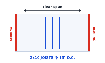 A floor framing plan: 2x10 joists spanning onto two bearing walls
What most framing plans have in common
Whatever part of the building it covers, a framing plan communicates the same essentials:
- Primary members, the repeating structural members spanning a space (joists in a floor, rafters or trusses in a roof), with their direction and on-center spacing.
- Beams and headers, larger members that gather loads and carry them to supports.
- Support walls, beams, and columns, where member reactions are intended to land.
- Openings, such as stairs, chases, and skylights, which interrupt the member field and need framing around them.
- Annotations, including member callouts, dimensions, spans, and a title block.
To decode the marks themselves, see the reference on framing plan symbols.
Choose the framing plan for the level
A coordinated drawing set may contain several framing plans. Each has a distinct job:
| Drawing | Primary intent | Coordination focus | Detailed guide |
|---|---|---|---|
| First-floor framing | Lay out the members supporting the floor at grade | Foundations, walls, beams, openings | Floor framing plan |
| Second-floor framing | Lay out an elevated floor | Stair opening and support on the first floor below | Second floor framing plan |
| Multi-level framing set | Coordinate several level drawings together | Vertical load paths and transfer locations | Two-story home framing plans |
| Roof framing | Lay out roof members and roof-plane geometry | Bearing, ridges, hips, valleys, openings, slope | Roof framing plan |
| Flat or low-slope roof framing | Coordinate a roof deck and its support | Drainage slope, drains, penetrations, roof loads | Flat roof framing plan |
Note the US floor numbering: the floor at grade is the first floor, and the floor above it is the second floor. The name of the sheet should identify both the level and the structure being shown. "Framing plan" with no level named is not enough on a project with more than one floor.
Who makes a framing plan, and when
A framing plan can exist at different issue stages:
- Preliminary layout, recording geometry and support assumptions for exploration and coordination. This is what Framing Plan produces.
- Design development or review, adding project loads, verified member selections, revised load paths, and coordination decisions.
- Issued construction information, including the sizes, details, connections, notes, revisions, and approvals required for its stated use.
Responsibility for preparing and approving structural information varies by jurisdiction and project. The title block and issue status tell you how a particular drawing may be used. Visual polish does not.
How to recognize a framing plan in a drawing set
Start with the sheet title: look for names such as floor framing plan, first floor framing, second floor framing, or a structural sheet number. Then confirm:
- The level and datum named in the title block.
- Parallel member lines with a span arrow and a joist or rafter callout.
- Beam, bearing, opening, and column tags leading to schedules or details.
- The revision and issue status, especially any preliminary or not-for-construction note.
Do not judge whether a drawing is current construction information from its appearance. A polished preliminary export can show joists and dimensions while still lacking verified design information.
What belongs on a coordinated set
A useful set makes cross-sheet relationships explicit:
- Every sheet names the correct level, datum, units, revision, and status.
- Floor and roof openings align with the current architectural background.
- Beams, columns, and bearing lines have support on the level below, or flag a transfer for design.
- Member tags lead to the correct schedule, section, or detail.
- Assumptions and unresolved items are visible rather than disguised as finished design.
For the hands-on drawing sequence, go to how to draft a preliminary floor framing plan. For marks and abbreviations, use framing plan symbols.
Framing plan vs architectural floor plan
An architectural floor plan arranges spaces, walls, doors, and fixtures. A framing plan coordinates the structural members and supports for one level. The two must agree on geometry and openings, but they are not interchangeable. The full comparison is in floor framing plan vs floor plan.
Keep it preliminary
A framing plan drafted in the browser is a preliminary layout aid. It is not evidence that spans, member sizes, bearing, connections, or code requirements have been checked. Those items need the project-specific structural design and approval required by the jurisdiction adopting your building code.
Make one now
Choose the level you are documenting, draft the preliminary geometry, and export it for coordination. Open the framing studio, then continue with the floor framing plan guide, the second floor guide, or the roof framing plan guide.