Wall framing is the skeleton of vertical studs held between a bottom (sole) plate and a double top plate, with headers, jack studs and cripples framing each door and window opening. In the US almost every house wall is a stud wall built this way, one story at a time on top of the floor deck (platform framing).
This guide names every part of a framed wall, explains how a wall framing diagram reads, and quotes the 2021 IRC where it sets a requirement. For where walls sit in the bigger drawing set, start with what a framing plan is.
What is a stud wall?
A stud wall is a wall built from repeated vertical members (studs) at a regular on-center spacing, capped and based by horizontal plates, then sheathed with drywall, plywood or OSB. The studs carry vertical load down to the plate and resist wind pushing on the face of the wall.
The 2021 IRC puts the core rule simply in Section R602.3: studs must be continuous from support at the sole plate to support at the top plate, and that support must be a foundation, a floor, or a ceiling or roof diaphragm (or be engineered). Jack, trimmer and cripple studs at openings are the stated exception, because they are short by design.
Parts of a framed wall
Here is the vocabulary you will see on a house framing diagram, from the floor up.
| Part | What it is | What it does |
|---|---|---|
| Bottom (sole) plate | Horizontal 2x member nailed to the floor deck or sill | Holds stud bottoms in line and gives them full bearing |
| Common studs | Full-height verticals at the wall's spacing, usually 16" or 24" o.c. | Carry vertical load and resist wind on the wall face |
| Top plates (double) | Two horizontal 2x members across the stud tops | Tie the wall together and pick up joists, rafters or trusses |
| King stud (full-height stud) | Full-height stud beside an opening | Braces the header end and the jack stud |
| Jack (trimmer) stud | Shorter stud nailed to the king stud | Carries the header end down to the bottom plate |
| Header | Beam over a door or window opening | Carries load above the opening to the jack studs |
| Cripple studs | Short studs above a header or below a rough sill | Fill the wall between the opening and the plates |
| Rough sill | Horizontal member at the bottom of a window opening | Frames the bottom of the rough opening |
Plates
R602.3.4 requires studs to have full bearing on a nominal 2-by (or larger) plate or sill at least as wide as the studs. R602.3.2 requires wood stud walls to be capped with a double top plate that overlaps at corners and at intersections with bearing partitions. End joints in the top plates must be offset at least 24 inches, and joints in plates need not occur over studs. The plates must be at least 2-inch nominal thickness and at least as wide as the studs.
The fastening schedule (Table R602.3(1), item 14) backs this up for a double top plate splice: a minimum 24-inch lap splice length on each side of the end joint, face nailed. A single top plate is allowed only under the R602.3.2 exception, which requires steel splice plates at corners, intersections and butt joints per Table R602.3.2, and rafters or joists centered over studs within 1 inch.
Studs
Stud size, height and spacing come from Table R602.3(5). The short version: 2x4 and 2x6 studs are the usual choices, and 16" or 24" o.c. the usual spacings, but the allowed spacing depends on how many floors the wall carries. That table is quoted in full in the stud spacing guide. R602.2 sets the minimum grade: No. 3, standard or stud grade lumber, with a utility-grade exception for limited cases.
Opening framing: king, jack, header, cripples and sill
An opening interrupts studs, so the load above it has to be collected and moved sideways. The header spans the opening. Each end of the header sits on one or more jack studs (also called trimmer studs), or on approved framing anchors, per R602.7.5. Beside each jack is a full-height stud, which framers call the king stud, end nailed into the header. Cripple studs fill the gap between the header and the top plate, and between the rough sill and the bottom plate under a window.
How many jack studs and how many full-height studs you need is not a fixed rule. The jack stud count comes from the header span tables (the NJ column in Tables R602.7(1) and R602.7(2)), and Table R602.7.5 sets the minimum number of full-height studs at each end of a header in exterior walls based on header span and wind exposure. Header sizes are covered in the header size chart.
In nonbearing walls, R602.7.4 says load-bearing headers are not required. A single flat 2x4 may serve as the header for openings up to 8 feet wide if the vertical distance to the parallel nailing surface above is not more than 24 inches, and no cripples or blocking are needed above it.
Reading a wall framing diagram
A wall framing diagram (sometimes called a wall elevation or framing elevation) shows one wall as if you were standing in front of it with the finishes stripped off. Read it in this order:
- Find the plates and confirm whether the top is a double plate.
- Check the stud layout callout, for example
2x6 STUDS @ 16" O.C., and where the layout starts. - Locate each opening and its rough opening size.
- At each opening, count the king and jack studs and read the header callout.
- Note corners and wall intersections, which need extra studs or backing (see California corner framing).
A floor framing plan, by contrast, shows walls in plan view as lines that support joists. The load-bearing walls guide explains how those lines are read.
Interior wall framing and partition walls
What is a partition wall?
A partition wall is any wall that divides space inside the building. Partitions come in two kinds, and the difference matters more than anything else about them:
- Bearing partitions carry floor, ceiling or roof load. R602.4 requires interior load-bearing walls to be constructed, framed and fireblocked as specified for exterior walls.
- Nonbearing partitions carry only their own weight and finishes. R602.5 allows them to be framed with 2x3 studs at 24 inches on center, or, where not part of a braced wall line, with 2x4 flat studs at 16 inches on center. They need not less than a single top plate and must be fireblocked per R602.8.
Do not decide a wall is nonbearing by looking at it. Joist direction, what sits above, and point loads all matter, and a wall that looks like a partition can be a load-bearing wall in the floor framing plan.
Notching and boring studs
Plumbing and wiring pass through interior walls, so the R602.6 limits are worth knowing. In exterior walls and bearing partitions a stud may not be notched more than 25 percent of its depth. In nonbearing partitions the notch limit is 40 percent of a single stud depth. Bored holes may not exceed 60 percent of the stud depth, must be at least 5/8 inch from the stud edge, and cannot sit in the same section as a notch. Where a bored hole in an exterior or bearing stud is over 40 percent, the stud must be doubled, and no more than two successive doubled studs may be bored that way.
Platform framing vs balloon framing
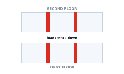 Bearing walls stacking from one story to the next
Platform framing builds one story at a time. The first floor deck goes down, walls are framed flat on it and tilted up, then the next floor deck sits on those walls' top plates and the process repeats. Studs only run one story, the deck gives a safe working surface, and each floor level naturally breaks the stud cavity.
Balloon framing runs the studs continuously from the sill to the top of the wall, passing the floor levels. Floor joists hang off a ledger let into the studs or nail to the sides of them. It needs long studs and leaves open cavities from floor to floor, which is why fireblocking at floor and ceiling levels is so important in this kind of wall. R602.8 requires fireblocking in accordance with Section R302.11.
You will still see balloon framing in older houses and occasionally in tall gable or stair walls where a continuous stud is wanted. For new US houses, platform framing is the default.
What this does not cover
Wall bracing (R602.10) decides how much sheathed wall each braced wall line needs and where it goes. It depends on wind speed, seismic design category and building geometry, and it is a separate check from stud size. Fastening schedules, uplift connectors and engineered walls are also outside this overview. The tables quoted above are prescriptive limits for their stated conditions only. Your jurisdiction's adopted code edition and local amendments govern, and engineered products such as LVL headers or I-joists use the manufacturer's tables.
Draw the floor the walls stand on
Wall layout drives where the floor joists bear. Framing Plan is a preliminary drawing aid for floor and roof framing layouts: it draws joist fields, beams and openings and exports PNG, PDF and DXF. Its bundled sample span profile uses demo figures and the editor works in millimetres, so it does not check code spans. Open the framing studio to sketch the joists over your wall lines, then have the layout verified for your project.