A deck framing plan is a top-down drawing of the deck structure: the ledger or freestanding support line, joists with size and spacing, the rim joist, beams, posts, footings, and blocking, all dimensioned and labeled. For a permit it must also state the design load, species and grade, connectors, and ledger fastening so a plan reviewer can check it against the code tables.
A deck plan uses the same conventions as any floor framing plan: joist fields with a span arrow, beams as heavy lines, and a callout like 2x10 JOISTS @ 16" O.C. for each bay. What changes is the support system. A deck usually hangs one edge on a ledger and carries the other edge on a beam, posts, and footings.
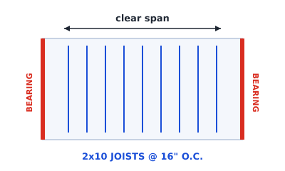 Joist span direction shown with arrows between support lines
The parts of a deck framing diagram
Ledger
The ledger is the board bolted to the house band joist that carries the inboard end of the joists. The 2021 IRC Section R507.9.1.1 sets the minimum at 2-inch by 8-inch nominal, treated or naturally durable, No. 2 grade or better. It may not carry concentrated loads from beams or girders, and it may not be fastened to stone or masonry veneer. The house band joist behind it must be at least 2-inch nominal solid-sawn spruce-pine-fir or better, or a 1-inch nominal engineered rim board (R507.9.1.2).
Joists
Joists run from the ledger to the beam, and often cantilever past the beam. Their size, spacing, and allowable span come from 2021 IRC Table R507.6, and the decking sets the maximum spacing through Table R507.7. Those tables are covered in the deck joist span and spacing chart. Deck joists do not use the interior floor joist span table, because the deck table includes the wet service factor for exterior lumber.
Rim joist or band joist
The rim joist caps the outer ends of the joists. On a deck it often doubles as lateral restraint: R507.6.2 says a rim joist used for that purpose must be secured to the end of each joist with at least three 10d (3-inch by 0.128-inch) nails or three No. 10 by 3-inch wood screws. The rim joist guide explains the member in more depth.
Beams
The beam (sometimes called a girder or drop beam) is the built-up member under the outboard joist ends. Its allowable span depends on the effective joist span it supports.
Posts and footings
Posts carry the beam down to footings. Table R507.4 limits post height, measured from the underside of the beam to the top of the footing or pier. Footings must sit at least 12 inches below undisturbed ground (R507.3.2), and where the deck is attached to a frost-protected structure they must also be protected from frost, for example by extending below the frost line.
Blocking
Blocking between joists provides lateral restraint at bearing lines and backing for guard posts and picture frame borders. Where blocking or hangers provide lateral restraint, R507.6.2 requires their depth to be at least 60 percent of the joist depth. General floor blocking rules are in joist blocking and bridging.
Picture frame border
A picture frame border is a band of deck boards running parallel to each edge. Those boards run the other way from the field boards, so the plan needs short joists or ladder blocking at the border so each board end and seam lands on support. Draw that framing on the plan and label it. The spacing comes from the decking manufacturer, not a generic rule.
Attached vs freestanding deck framing
An attached deck relies on the ledger. R507.8 requires a positive connection to the house designed for vertical and lateral loads, and forbids toenails or nails subject to withdrawal. Where the inspector cannot verify a positive connection to the house structure, the deck must be self-supporting.
A freestanding deck replaces the ledger with a second beam on its own posts and footings. Two narrow exceptions in R507.3 allow no footings: joists bearing directly on grade over their full length, or joists on precast pier blocks at grade, with no beams or posts, on a deck of 200 square feet or less whose walking surface is no more than 20 inches above grade within 36 inches of the edge.
Key numbers from 2021 IRC Section R507
All values below are the unamended 2021 IRC tables for a 40 psf live load, 10 psf dead load, No. 2 grade, wet service factor included. Some states amend them. The Washington edition used as the source here replaces several 40 psf tables with 60 psf live load versions, so check what your jurisdiction adopted.
Deck beam spans
To read the beam table you need the effective deck joist span: the actual joist span multiplied by a factor from Table R507.5(5). The factor is 0.66 with no joist cantilever and 1.00 where the cantilever is one-quarter of the joist span. A 12-foot joist span with no cantilever gives 12 x 0.66 = 7.9 feet, so you read the 8-foot column.
2021 IRC Table R507.5(1), maximum deck beam span (feet-inches), 40 psf live load, 10 psf dead load, No. 2 grade, L/Δ = 360 at main span.
| Beam | Southern pine, 8 ft | Southern pine, 10 ft | Southern pine, 12 ft | DF-L / HF / SPF, 8 ft | DF-L / HF / SPF, 10 ft | DF-L / HF / SPF, 12 ft |
|---|---|---|---|---|---|---|
| 2-2x10 | 9-0 | 8-0 | 7-4 | 8-7 | 7-9 | 7-0 |
| 2-2x12 | 10-7 | 9-5 | 8-7 | 10-0 | 8-11 | 8-2 |
| 3-2x10 | 11-2 | 10-0 | 9-2 | 10-10 | 9-8 | 8-10 |
| 3-2x12 | 13-3 | 11-10 | 10-9 | 12-7 | 11-3 | 10-3 |
Column headings are effective deck joist span. Beam cantilevers are limited to the adjacent beam span divided by 4. For a flush beam, beam depth must be at least the depth of the intersecting joists. Interpolation is permitted, extrapolation is not.
Deck post heights
In Table R507.4 at 40 psf, a 6x6 post in Southern pine or the Douglas fir-larch, hem-fir, spruce-pine-fir group is listed at 14-0 for every tributary area from 20 to 160 square feet. A 4x4 drops off fast: in Southern pine it is 13-8 at 40 square feet and 9-5 at 80 square feet. Tributary area is the deck surface supported by that post and footing.
Ledger fastener spacing
2021 IRC Table R507.9.1.3(1), on-center spacing of ledger fasteners (inches), 40 psf live load, 10 psf dead load.
| Joist span | 1/2" lag screw, max 1/2" sheathing | 1/2" bolt, max 1/2" sheathing | 1/2" bolt, max 1" sheathing |
|---|---|---|---|
| 8 ft | 23 | 36 | 36 |
| 12 ft | 15 | 29 | 24 |
| 16 ft | 11 | 21 | 18 |
Fasteners must be hot-dipped galvanized or stainless steel, staggered per Table R507.9.1.3(2), and the ledger must be flashed so water cannot reach the house band joist. The tip of a lag screw must extend fully past the inside face of the band joist.
How to draw a deck framing plan for a permit
- Draw the deck outline at scale from a measured house wall, with overall dimensions and the house wall labeled.
- Mark the support line at the house: a ledger with size, fastener type, and spacing, or a second beam for a freestanding deck.
- Lay out the joist field with a span arrow and a callout giving size, species, and spacing, e.g.
2x8 SYP JOISTS @ 16" O.C.Dimension the joist span and any cantilever separately. - Place the beam with ply count and size (
(2) 2x10 BEAM), and dimension its spans between posts and any beam cantilever. - Locate posts and footings with dimensions to a reference line, post size, footing diameter or size, and depth.
- Add blocking, the rim joist, and picture frame framing, plus joist hangers at the ledger and connectors at post-to-beam and post-to-footing.
- Write the general notes: design live load, lumber species and grade, preservative treatment, fastener and connector corrosion protection, and the code or guide you followed.
Pair the plan with a cross section showing heights, the ledger detail, and guard posts. Reviewers check the section against the plan, so the dimensions must agree.
Labels a plan reviewer expects
- Design live load (and ground snow load if it governs)
- Joist size, species, grade, spacing, span, and cantilever
- Beam size, plies, spans, and cantilevers
- Post size and height, footing size and depth below grade
- Ledger size, fastener type, diameter, spacing, and flashing
- Joist hangers and post connectors by type
- Decking material and orientation (it controls joist spacing)
- Lateral load connection where the deck is attached, per R507.9.2
- Guard height and post attachment
The framing plan symbols guide covers the line types and tags, and how to read a floor framing plan explains how reviewers scan a sheet.
Use DCA 6 and your local code
The American Wood Council publishes DCA 6, its prescriptive residential wood deck construction guide, which many building departments accept as a deck design reference. The adopted code edition and local amendments still govern, and engineered lumber, steel framing, and composite decking follow manufacturer tables and instructions. Tables cover only the conditions stated in them.
Try it
Framing Plan is a preliminary drawing aid. It draws joist layouts, beams, and openings, and exports PNG, PDF, and DXF, but it does not check deck spans against R507. Use it to lay out the deck, then confirm each member against the tables above. Open the framing studio to sketch your deck framing plan.