A sill plate is the wood member bolted flat to the top of a foundation wall, and it is where the wood frame of a house meets the concrete. Under 2021 IRC Section R403.1.6 it is held down with anchor bolts at least 1/2 inch in diameter, spaced not more than 6 feet on center and embedded at least 7 inches into the concrete.
All values below come from the 2021 International Residential Code. The code edition your jurisdiction has adopted, plus any local amendments, governs, and proprietary anchors and straps are installed to the manufacturer's data.
What is a sill plate?
The sill plate (also called the mudsill or sill) is usually a 2x member laid flat on the foundation wall. It does three jobs:
- Bearing. Floor joists and the rim joist sit on it, so floor and wall loads pass through it into the foundation.
- Anchorage. Anchor bolts cast into the concrete pass up through the plate. A nut and washer on each bolt clamp the wood to the foundation so the building cannot slide or lift off.
- Separation. It is the piece of wood closest to the concrete and the ground, which is why the decay protection rules in Section R317 apply to it.
Over a crawl space or raised floor, the sill sits on a stem wall, the short foundation wall between the footing and the floor framing.
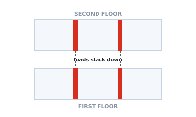 Load path from roof and walls through the floor and sill plate into the foundation
Sill plate anchor bolt spacing
The basic anchor bolt requirements apply to all wood sill plates, to wood sole plates at all exterior walls on monolithic slabs, and to sole plates of braced wall panels at building interiors on monolithic slabs.
2021 IRC Section R403.1.6: foundation anchorage of wood sill plates and qualifying sole plates, all seismic design categories.
| Requirement | 2021 IRC value |
|---|---|
| Minimum anchor bolt diameter | 1/2 inch |
| Maximum anchor bolt spacing | 6 feet on center |
| Minimum embedment | 7 inches into concrete or grouted cells of concrete masonry units |
| Bolt location across the plate | Middle third of the width of the plate |
| Bolts per plate section | Not fewer than two |
| End bolt location | Not more than 12 inches or less than seven bolt diameters from each end of the plate section |
| Hardware | A nut and washer tightened on each bolt |
Approved anchors or anchor straps are allowed instead of bolts if they are spaced to give anchorage equivalent to 1/2-inch-diameter anchor bolts. That spacing comes from the strap manufacturer's data, not from the IRC.
Rules that catch people out
- Every plate section counts. A plate section is each separate length of sill. A short piece between a corner and a splice still needs two bolts, and the end bolt rule applies at both ends of each piece.
- Wet setting is allowed. Bolts may be placed while the concrete is still plastic and before it has set. Where the bolts resist placement or the concrete does not consolidate around them, the concrete has to be vibrated so it makes full contact with the bolts.
- Short offset walls. Exception 1 lets a wall 24 inches or shorter connecting offset braced wall panels use one anchor bolt in the center third of the plate section. Exception 2 lets a wall 12 inches or shorter skip anchor bolts entirely. Both must be attached to the adjacent braced wall panels at the corners per Item 9 of Table R602.3(1).
- Interior bearing walls on a slab. Interior bearing wall sole plates on a monolithic slab that are not part of a braced wall panel need positive anchorage with approved fasteners, not necessarily anchor bolts.
Foundation anchor bolts in high seismic areas
Section R403.1.6.1 adds requirements for wood light-frame structures in Seismic Design Categories D0, D1 and D2, and for wood light-frame townhouses in Seismic Design Category C.
2021 IRC Sections R403.1.6.1 and R602.11.1: additional foundation anchorage, SDC D0, D1 and D2 and townhouses in SDC C.
| Item | Requirement |
|---|---|
| Plate washers | Required on all anchor bolts over the full length of required braced wall lines, unless approved anchor straps are used |
| Plate washer size | Not less than 0.229 inch by 3 inches by 3 inches, between the sill plate and the nut |
| Slotted plate washer | Diagonal slot up to 3/16 inch wider than the bolt diameter and not longer than 1-3/4 inches, with a standard cut washer between the plate washer and the nut |
| Wall lines without braced wall panels | Properly sized cut washers permitted |
| Interior braced wall plates | Bolts at not more than 6 feet on center and within 12 inches of the ends of each plate section, where on a continuous foundation |
| Interior bearing wall sole plates | Bolts at not more than 6 feet on center and within 12 inches of the ends of each plate section, where on a continuous foundation |
| Buildings over two stories in height | Maximum anchor bolt spacing of 4 feet |
Stepped cripple walls follow Section R602.11.2, and continuous wood foundations built to Section R404.2 have their own force transfer rule in item 6 of R403.1.6.1.
Pressure treated sill plate requirements
Section R403.1.6 says sill plates and sole plates shall be protected against decay and termites where required by Sections R317 and R318. Section R317.1 requires naturally durable wood, or wood preservative-treated to AWPA U1, in these locations that commonly involve a sill:
2021 IRC Section R317.1: locations requiring decay protection that apply to sill plates and nearby framing.
| R317.1 item | Location |
|---|---|
| 1 | In crawl spaces, wood joists or the bottom of a wood structural floor closer than 18 inches to exposed ground, and wood girders closer than 12 inches to exposed ground |
| 2 | Wood framing members, including columns, resting directly on concrete or masonry exterior foundation walls and less than 8 inches from exposed ground |
| 3 | Sills and sleepers on a concrete or masonry slab in direct contact with the ground, unless separated from the slab by an impervious moisture barrier |
| 5 | Wood siding, sheathing and wall framing on the exterior with less than 6 inches clearance from the ground, or less than 2 inches measured vertically from concrete steps, porch slabs, patio slabs and similar surfaces exposed to the weather |
Two follow-on rules matter on site. Section R317.1.1 requires field-cut ends, notches and drilled holes in preservative-treated wood to be field treated per AWPA M4, which includes the holes you drill for the anchor bolts. Section R317.1.2 requires wood in contact with the ground, or embedded in concrete in contact with the ground, to be pressure-preservative-treated wood suitable for ground contact. A sill sitting on top of a foundation wall is not normally in ground contact, but a plate set below grade could be. Termite protection under Section R318 depends on your area; the building department will say what applies.
Sill gasket and sill sealer
A sill gasket is a foam or rubber strip laid on the foundation before the sill plate goes down. It fills the gaps between rough concrete and the flat underside of the plate, cutting air leakage at the base of the wall. Some products also act as a capillary break between concrete and wood.
The foundation and decay sections used here do not require one. Air sealing requirements come from the energy code your jurisdiction has adopted. Do not assume a foam gasket counts as the impervious moisture barrier in R317.1 item 3; if you want to use untreated sills on a slab on that basis, get the building official's agreement first.
Sill plate vs sole plate
2021 IRC Sections R403.1.6 and R602.3.4: comparison of sill plates and sole (bottom) plates.
| Sill plate | Sole (bottom) plate | |
|---|---|---|
| Sits on | Concrete or masonry foundation | Subfloor, or a monolithic slab |
| Carries | Floor joists and rim joist, or wall studs | Wall studs |
| Anchorage | Anchor bolts per R403.1.6 | Nailed to the floor framing; anchored per R403.1.6 at exterior walls and interior braced wall panels on a monolithic slab |
| Decay protection | Usually required by R317.1 | Required where R317.1 applies, such as on a slab in contact with the ground |
Section R602.3.4 requires studs to have full bearing on a nominal 2-by or larger plate or sill at least as wide as the studs. On a slab-on-grade house the exterior wall sole plate is effectively doing the sill's job and follows the same bolt rules. More on plates and studs is in wall framing basics.
Fastening joists to the sill
Table R602.3(1) Item 22 covers a joist to sill, top plate or girder connection as a toe nail with 4-8d box (2-1/2 inch x 0.113 inch), 3-8d common (2-1/2 inch x 0.131 inch), 3-10d box (3 inch x 0.128 inch), or 3 nails 3 inch x 0.131 inch. Rim joist nailing to the sill is covered in the rim joist article, and lateral restraint at supports is covered in joist blocking and bridging.
Showing the sill plate on a framing plan
On a floor framing plan the sill is usually shown as the foundation outline with a note giving its size, the treatment, and the anchor bolt diameter, spacing and embedment, with a section reference for the detail. Interior bearing lines on the foundation need the same note, as described in load-bearing walls in a floor framing plan. The line types and tags are in framing plan symbols. A deck ledger is a different connection and is covered in the deck framing plan guide.
Framing Plan draws joist layouts, beams and openings and exports PNG, PDF and DXF. It does not check anchorage or any other code requirement: the editor works in millimeters and its sample profile uses demo span figures and metric member sizes, so treat its output as a preliminary drawing aid. Confirm the anchor bolt layout with the code sections above, then open the framing studio to lay out the floor framing that sits on the sill and hand the drawing to your designer or plan reviewer.