Steel stud framing is built to Section R603 of the 2021 International Residential Code (IRC) when the walls are exterior or load-bearing, and to AISI S220 when the walls are interior nonbearing partitions. R603 prescribes screws, anchorage, in-line framing, headers and bracing for buildings up to three stories.
Steel stud framing, also called metal stud framing or cold-formed steel framing, uses C-shaped studs and U-shaped tracks formed from sheet steel in place of dimension lumber. The studs sit inside the track at the floor and ceiling, and everything is joined with screws rather than nails. Most people searching "metal stud framing" want interior partitions, and for those the IRC says very little. This article covers both, and says plainly where the code stops and the manufacturer takes over.
Key facts
- Section R603.1.1 of the 2021 IRC covers exterior and interior load-bearing cold-formed steel walls in buildings up to three stories above grade plane, 60 feet long perpendicular to the joist or truss span and 40 feet wide parallel to it.
- Section R603.1.1 limits the prescriptive method to sites with an ultimate design wind speed below 140 miles per hour, Exposure Category B or C, and a ground snow load of 70 psf or less.
- Section R603.2.5 requires screws to extend through the steel by at least three exposed threads and to be self-drilling tapping screws conforming to ASTM C1513.
- Section R603.1.2 requires load-bearing steel studs to be located in line with the joists, trusses and rafters above them, within the tolerances in AISI S240, Section B1.2.3.
- Section R603.3.4 prohibits cutting or notching the flanges and lips of steel studs and headers.
- Section R702.3.3 requires framing that supports gypsum board to be at least 1-1/4 inches wide in its least dimension.
What does the IRC say about steel stud framing?
Section R603 is a full prescriptive method for exterior and interior load-bearing walls. Interior walls that carry no load get a one-line reference to another standard.
| Wall type | Governing source | What the IRC gives you |
|---|---|---|
| Exterior walls | 2021 IRC Section R603 | Stud tables, fastening, anchorage, headers, sheathing |
| Interior load-bearing walls | 2021 IRC Section R603 | Same tables, read at 115 mph, Exposure B, per R603.3.2 |
| Interior nonbearing partitions | AISI S220, via 2021 IRC Section R702.3.3 | Reference only, no gauge or height table |
| Buildings beyond the R603.1.1 limits | AISI S230, per Section R603.1.1.1 | Alternate design route, subject to its own limits |
Basis: 2021 IRC Sections R603.1.1, R603.1.1.1, R603.3.2 and R702.3.3.
Section R603.1.1 treats exterior walls built under R603 as load-bearing walls. For which walls carry load on a plan, see the load-bearing walls guide.
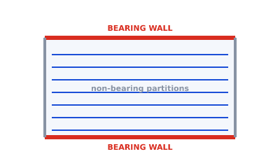 Bearing walls and nonbearing partitions on a framing plan
What are the limits for steel stud framing in the IRC?
The prescriptive method applies only inside the Section R603.1.1 limits listed under Key facts: three stories, 60 by 40 feet, under 140 miles per hour, Exposure Category B or C, and 70 psf ground snow load or less.
Outside those limits, Section R603.1.1.1 permits design and construction under AISI S230, subject to the limits in that standard. The adopted code edition and local amendments govern, so confirm what your jurisdiction has adopted before relying on any table.
What is in-line framing for steel studs?
In-line framing means each load-bearing steel stud sits directly under the joist, truss or rafter it supports. Section R603.1.2 requires this for load-bearing studs, within the tolerances in AISI S240, Section B1.2.3. Draw stud and joist or truss spacing on the same grid so the alignment is visible. The stud spacing article covers the wood equivalents.
How is steel stud framing made and identified?
Sections R603.2.1 to R603.2.4 and R603.2.6 point to AISI S240 and S230 for material, corrosion protection, dimensions, product identification and web holes rather than reproducing them. The stud tables label members with designations such as 350S162 for studs and 350T125-33 for tracks, with thickness in mils. Read the designation on the bundle tag against the table, not against a gauge number from memory.
What screws do you use for steel stud framing?
Use self-drilling tapping screws conforming to ASTM C1513 for steel-to-steel connections, sized by what you are fastening. Section R603.2.5 sets the rules, and Table R603.3.2(1) sets the schedule.
2021 IRC Table R603.3.2(1), wall fastening schedule (all screw sizes are minimums).
| Building element | Fasteners | Spacing |
|---|---|---|
| Wall stud to top or bottom track | 2 No. 8 screws | Each end of stud, one per flange |
| Structural sheathing to wall studs | No. 8 screws | 6 inches on center on edges, 12 inches on center at intermediate supports |
| 1/2 inch gypsum board to framing | No. 6 screws | 12 inches on center |
Section R603.2.5 adds three details:
- Screws for steel-to-steel connections need a minimum edge distance and center-to-center spacing of 1/2 inch.
- Structural sheathing screws need a minimum head diameter of 0.292 inch and a minimum edge distance of 3/8 inch.
- Fasteners need a rust-inhibitive coating, or must be made of a material not susceptible to corrosion.
For drywall over steel, Section R702.3.5.1 repeats the No. 6 minimum. Screw spacing for the board itself is in the drywall screw spacing guide.
How far apart should metal studs be spaced?
For load-bearing steel walls, the stud tables are written for 16 inch and 24 inch spacing, and the thickness needed rises as spacing widens. Section R603.3.2 sends you to Tables R603.3.2(2) through R603.3.2(16), selected by building width, stud height, stud spacing, wind speed, exposure and ground snow load.
There is no single metal stud spacing for bearing walls: the cell you need depends on the building, so read it from the printed table.
Section R603.3.2 allows an exterior wall stud to drop to the next thinner size, but not below 33 mils, where at least 1/2 inch gypsum board is fastened on the interior surface and at least 7/16 inch oriented strand board or 15/32 inch plywood is fastened on the outside. Interior load-bearing walls can drop one size, again not below 33 mils, with at least 1/2 inch gypsum board on both sides.
For interior nonbearing partitions, the IRC gives no spacing table. Section R702.3.3 says nonload-bearing steel framing must comply with AISI S220, so use the stud manufacturer's tables for gauge, spacing and limiting height. For general wall layout, wall framing basics shows the standard parts of a framed wall.
How is a steel stud wall anchored?
Anchorage depends on what the wall sits on and the design wind speed. Section R603.3.1 requires anchorage to foundations or floors under Table R603.3.1 and Figures R603.3.1(1) to R603.3.1(4). Anchor bolts must be within 12 inches of corners and of the termination of bottom tracks, and must extend at least 15 inches into masonry or 7 inches into concrete. Foundation anchor straps may replace anchor bolts if spaced to give equivalent anchorage and installed per the manufacturer.
2021 IRC Table R603.3.1, wall bottom track to floor and to foundation, by ultimate wind speed (mph) and exposure category.
| Connection | 115 B | 120 B | 130 B or 115 C | under 140 B or 120 C | 130 C | under 140 C |
|---|---|---|---|---|---|---|
| Bottom track to floor, per Figure R603.3.1(1) | 1 No. 8 screw at 12 in. | 1 No. 8 screw at 8 in. | 2 No. 8 screws at 8 in. | 2 No. 8 screws at 6 in. | 3 No. 8 screws at 8 in. | 3 No. 8 screws at 6 in. |
| Bottom track to foundation, per Figure R603.3.1(2) | 1/2 in. anchor bolt at 6 ft | 1/2 in. anchor bolt at 6 ft | 1/2 in. anchor bolt at 4 ft | 1/2 in. anchor bolt at 4 ft | 1/2 in. anchor bolt at 3 ft 4 in. | 1/2 in. anchor bolt at 2 ft 8 in. |
The table also covers bottom track to a wood sill (Figure R603.3.1(3)) and wind uplift connector strengths. Read those cells in the printed table. For the wood sill itself, see the sill plate guide.
How are openings, bracing and sheathing handled?
Each of these has its own table in Section R603.
- Headers (R603.6): required above all openings in exterior walls and interior load-bearing walls. Box beam and back-to-back headers are formed from two equal-sized C-shaped members and sized from Tables R603.6(1) through R603.6(6). The header size chart covers the wood equivalent.
- Jack and king studs (R603.7): counted from Table R603.7(1) by opening size and stud spacing. An opening up to 3 feet 6 inches takes 1 jack stud and 1 king stud at each end at either 16 or 24 inch spacing.
- Head and sill track (R603.8): spans come from Table R603.8.
- Stud bracing (R603.3.3): gypsum board or structural sheathing on the walls, or horizontal steel straps at least 1-1/2 inches wide and 33 mils thick.
- Structural sheathing (R603.9): at least 7/16 inch oriented strand board or 15/32 inch plywood. The wall sheathing article covers sheathing in general.
Section R603.3.4 prohibits cutting or notching flanges and lips of steel studs and headers, and Section R603.3.5 prohibits splicing studs and other structural members without an approved design.
How do steel walls appear on a framing plan?
Steel framing uses the same wall lines as wood, with different callouts. Label load-bearing steel walls by stud designation, thickness in mils and spacing, and mark each wall as bearing or nonbearing. Note the wind speed, exposure and snow load you used, and name the table.
Draw interior nonbearing partitions as partitions, with a note referring to the manufacturer's tables and AISI S220. The framing plan symbols guide shows how to separate wall types in the legend.
Summary
Steel stud framing is covered by Section R603 of the 2021 IRC for exterior and interior load-bearing walls, within limits of three stories, 60 by 40 feet, under 140 mph wind and 70 psf ground snow load. Use No. 8 screws for sheathing, No. 6 for gypsum board, keep studs in line with joists above, and do not cut or notch flanges. Interior nonbearing partitions fall under AISI S220 through Section R702.3.3, so take gauge and height from the manufacturer. These are prescriptive values only: the adopted code edition and local amendments govern.
Framing Plan is a preliminary drawing aid that draws joist layouts, beams and openings and exports PNG, PDF and DXF. It does not check steel stud sizes or code compliance. Open the framing studio to lay out the floor and wall lines your steel studs will sit under, then hand the drawing to your designer or plan reviewer.