A ridge board is a non-structural nailing plate where rafters meet; a ridge beam is a structural beam that holds up the top end of the rafters and carries that load to posts or walls. You can use a ridge board only when ceiling joists or rafter ties tie the walls together across the building. Without those ties, the 2021 IRC requires a designed ridge beam.
The choice changes the whole roof framing plan: a ridge beam needs posts, a load path to the foundation, and an engineered size, while a ridge board needs a continuous tie at the bottom of every rafter pair.
How a ridge board roof works
Picture two rafters leaning against each other like an A-frame. Gravity pushes the tops together and the bottoms outward. In a ridge board roof:
- The rafters bear against each other through the ridge board, which is just a plate to nail them to and keep them aligned.
- The outward push at the bottom of each rafter (the thrust) is held by ceiling joists or rafter ties nailed to the rafters at the wall plate. These act as a tension tie, like the string of a bow.
- The walls only carry vertical load.
Take the ties away and the rafters flatten out, the ridge sags, and the top of the walls bow outward. That is the classic failure in old houses where someone removed ceiling joists to open up a room.
Section R802.2 states the principle: the roof and ceiling assembly shall provide continuous ties across the structure to prevent roof thrust from being applied to the supporting walls.
Ridge board size
2021 IRC R802.3: a ridge board used to connect opposing rafters shall be not less than 1 inch nominal thickness and not less in depth than the cut end of the rafter. On a steep roof the plumb cut on a 2x8 rafter is deeper than the 2x8 itself, so the ridge board is often one size up from the rafter. R802.4.2 also says opposing rafters must not be offset more than 1-1/2 inches from each other at the ridge and must be connected with a collar tie, ridge strap, or gusset plate.
How a structural ridge beam works
A structural ridge beam turns the roof into two sets of sloped joists. Each rafter spans from the wall plate up to the beam, and the beam carries the upper half of the rafter load to a post or bearing wall at each end. Because the top of each rafter is held up by the beam instead of by its opposite rafter, there is little or no outward thrust, and no ceiling ties are needed.
That load does not stop at the beam. It goes down the posts, through any floor below on blocked or stacked posts, to a footing. Ridge beam support is where most mistakes happen: a post that lands mid-span on a floor joist or on a header not sized for a point load. The post, its connection at the top, and the footing all belong on the plan. See load-bearing walls in a floor framing plan for how that load path is drawn.
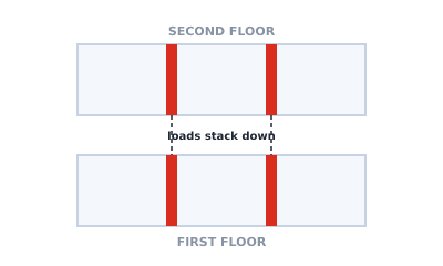 Load path from roof to foundation through stacked supports
When the IRC requires a ridge beam
The 2021 IRC sends you to a designed ridge in three cases.
| Condition | Code text | Result |
|---|---|---|
| Ceiling joists or rafter ties do not provide continuous ties across the structure | R802.3 | Ridge supported by a wall or ridge beam designed per accepted engineering practice, supported on each end by a wall or column |
| Ceiling joists installed above the bottom third of the rafter height | R802.5.2 | Ridge designed as a beam per R802.3 |
| Roof pitch less than 3:12 (25-percent slope) | R802.4.4 | Ridges, hips, and valleys designed as beams, with rafter bearing per R802.6 |
Where ceiling joists do not run parallel to the rafters, R802.5.2 says rafters shall be tied across the structure with a rafter tie per R802.5.2.2, or the ridge shall be designed as a beam.
Ceiling joists, rafter ties, and collar ties
These three are not interchangeable.
- Ceiling joists that run parallel to the rafters and sit in the bottom third of the rafter height act as the tie. They must be continuous across the building or lapped over an interior partition: R802.5.2.1 requires laps of not less than 3 inches, nailed per Table R802.5.2(1) where they form the tie.
- Rafter ties do the same job where the ceiling joists run the other way. R802.5.2.2 requires wood rafter ties of not less than 2 inches by 4 inches, installed per Table R802.5.2(1), at a maximum of 24 inches on center.
- Collar ties sit in the upper third of the attic space (R802.4.6) and resist uplift and ridge separation. They do not resist wall thrust, so they never replace ceiling joists or rafter ties.
The nailing at the heel joint (rafter to ceiling joist) grows with snow load, roof span, and rafter spacing, and falls as the pitch gets steeper. Table R802.5.2(1) gives the count of 16d common nails per heel joint. A small slice:
2021 IRC Table R802.5.2(1), required number of 16d common nails per heel joint, 30 psf ground snow load, rafter spacing 16" o.c., ties at the bottom of the attic space.
| Roof slope | 12 ft roof span | 24 ft roof span | 36 ft roof span |
|---|---|---|---|
| 4:12 | 3 | 6 | 9 |
| 7:12 | 3 | 4 | 5 |
| 12:12 | 3 | 3 | 3 |
Footnote b of that table states that heel joint connections are not required where the ridge is supported by a load-bearing wall, header, or ridge beam. Footnote f increases the nail count by the factors in Table R802.5.2(2) where ties are raised higher in the attic.
Cathedral ceilings need a structural ridge
A cathedral or vaulted ceiling with rafters exposed or finished on their underside has no ceiling joists across the room. Unless you can fit rafter ties in the bottom third of the rafter height, nothing holds the walls together, so the ridge has to be a beam. The same applies to raised-tie designs where the ties sit above the bottom third: R802.5.2 sends those to a designed ridge.
Low-slope roofs below 3:12 also need beams at the ridge because the rafters are so flat that thrust becomes very large for a given load.
Ridge beam size
The IRC has rafter span tables (see the rafter span chart) but no ridge beam span table. R802.3 says the beam is "designed in accordance with accepted engineering practice." In practice:
- Solid sawn ridge beams are sized by an engineer using the NDS.
- LVL, PSL, and glulam ridge beams are sized from the manufacturer's tables or software for the exact product, span, and roof load.
- The posts and the footing under each end are sized at the same time.
Do not borrow a header size from the header size chart for a ridge beam. Header tables cover short openings in bearing walls for set building widths, not a long beam carrying the upper half of every rafter along the ridge.
Ridge beam vs. ridge board on a framing plan
On a roof framing plan:
- A ridge board is drawn as a single line labeled with its size (for example
2x10 RIDGE BD), with the ceiling joists or rafter ties called out and a note on the heel nailing. - A ridge beam is drawn as a beam with its size and material, the posts at each end marked with a symbol and a post size, and a note tracing the load to the foundation.
For how hips and valleys tie in, read gable and hip roof framing. Trussed roofs avoid this question entirely because each truss has its own bottom chord as the tie; see roof truss types.
Keep it preliminary
The values above are prescriptive provisions of the 2021 IRC for the stated conditions only. Your adopted code edition and local amendments govern, and the roof provisions are in Chapter 8 of the 2021 IRC. Any structural ridge beam, its posts, and engineered lumber need sizing by a designer or from manufacturer tables.
Framing Plan can draw beams, posts, openings, and joist layouts and export them to PNG, PDF, or DXF so you have a clear sketch to take to an engineer or plan reviewer. It does not size ridge beams or check rafter spans.