A gable roof has two primary sloping planes and gable-end walls; a hip roof slopes toward the eaves on all sides. That changes the roof-plane geometry shown on the framing plan. The exact members depend on whether the project uses conventional rafters, engineered trusses, or another system.
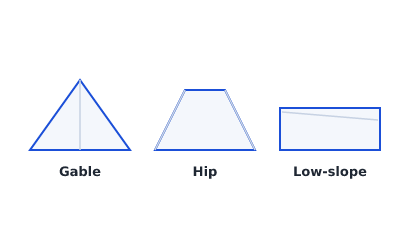 Gable, hip, and flat roofs compared
The gable roof
A gable roof has two sloping planes that meet at a ridge, with a vertical triangular gable wall at each end. On a simple conventional-rafter plan:
- Rafters run from the bearing walls up to the ridge, in two opposing sets.
- The plan shows a single ridge line down the middle, with rafters at a regular spacing on each side, commonly 16" or 24" on center.
- Gable-end wall, rake overhang, lookouts, bracing, and siding support may require their own framing and details.
A trussed gable roof is shown differently: the placement plan identifies repeated and special trusses, gable-end conditions, bearings, and bracing references.
The hip roof
A hip roof slopes on all sides, meeting at hips (the sloping lines at outside corners) and often a ridge. For a conventional-rafter scheme:
- Hip rafters run from each corner up toward the ridge.
- Jack rafters frame between the wall and the hip rafters, getting shorter toward the corner.
- The plan shows ridge and diagonal hip lines, plus the associated support and connection references.
An engineered hip-truss system uses a different sequence of truss types rather than simply reproducing conventional hip and jack rafters.
Side by side
| Gable | Hip | |
|---|---|---|
| Slopes | Two | Four |
| End walls | Vertical gable walls | Sloped (no gable) |
| Distinct conditions | Gable-end wall and rake details | Hip lines, corner reactions, and shorter infill members or special trusses |
| Plan complexity | Often lower for a simple rectangle | Often higher, but the system and footprint control |
What stays the same
Whichever geometry applies, the plan must identify the structural system, member or truss placement, support and bearing locations, openings, roof-plane geometry, bracing and connection references, and slope information. See rafters vs. trusses and roof pitch and slope.
A note on the tool
Framing Plan can sketch a plan-view footprint, support assumptions, openings, repeated joists, and annotations. It has no dedicated tools for roof planes, conventional rafters, ridges, hips, valleys, trusses, bracing, or connections. A low-slope roof may be represented preliminarily when its chosen system uses repeated joists. See flat roof framing plans.
Keep it preliminary
Pitched-roof structure carries significant loads. Use a preliminary plan to communicate layout intent: a qualified engineer or truss supplier must confirm the rafters, hips, and connections for your project and for the code adopted in your jurisdiction, where roof and ceiling framing sits in IRC Chapter 8.
Try it
For the plan-view layout or a flat roof, open the framing studio, or read the full roof framing plan guide.