Hurricane ties are rated metal connectors that hold rafters or trusses down to the wall top plate so wind cannot lift the roof off. The 2021 IRC requires a roof uplift connection at every rafter and truss, and Section R802.11 lets you rely on plain toe-nailing only when the tabulated uplift is 200 pounds or less or the roof meets a narrow low-wind exception.
This guide walks through Section R802.11, the uplift force table behind it, and how the connection carries on down through the walls. It is a preliminary drawing aid. The code edition your jurisdiction has adopted, plus any local amendments, governs. Truss uplift comes from the truss design drawings, and connector capacities come from the manufacturer's published ratings.
What hurricane ties and hurricane straps do
Wind over a roof creates suction that pulls the roof assembly upward. Gravity framing is built to push down on its supports, not to resist being pulled off them. A hurricane tie, strap, or clip is a steel framing connector nailed to a rafter or truss and to the top plate below, so uplift passes into the wall instead of prying out a few toe nails.
On site, "clip" or "tie" usually means a short connector at the rafter-to-plate joint, and "strap" a longer piece that runs down the wall. The code names no products. It asks for a connection "capable of resisting uplift forces," which in practice means a rated framing connector with a published uplift value.
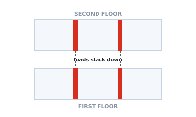 Uplift load path from the roof framing through the walls to the foundation
Are hurricane ties required?
2021 IRC Section R802.11 says roof assemblies shall have uplift resistance in accordance with Sections R802.11.1 (trusses) and R802.11.2 (rafters). There are two exceptions. Rafters or trusses may be attached with the ordinary nailing in Table R602.3(1) where either of the following applies:
- The uplift force per rafter or truss does not exceed 200 pounds, as determined by Table R802.11.
- The basic wind speed does not exceed 115 mph, the wind exposure category is B, the roof pitch is 5:12 or greater, the roof span is 32 feet or less, and rafters and trusses are spaced not more than 24 inches on center.
Miss both tests and the roof needs a connection sized for the tabulated or engineered force, which in practice means a hurricane tie.
Rafter ties to top plate when an exception applies
When an exception is met, 2021 IRC Table R602.3(1) item 6, "Rafter or roof truss to plate," calls for one of:
- 3-16d box (3-1/2" x 0.135")
- 3-10d common (3" x 0.148")
- 4-10d box (3" x 0.128")
- 4 nails, 3" x 0.131"
installed as 2 toe nails on one side and 1 toe nail on the opposite side of each rafter or truss. Footnote i to that table covers a rafter fastened to an adjacent parallel ceiling joist: two toe nails on one side of the rafter, with the ceiling joist toe-nailed to the plate, and the opposite-side toe nail is not required.
How to read Table R802.11
Table R802.11 gives rafter or truss uplift connection forces from wind, in pounds per connection (ASD). To find your value you need five inputs:
- Exposure category, B or C. Exposure D is not tabulated (see the footnotes below).
- Ultimate design wind speed, 110, 115, 120, 130, or 140 mph, from the wind map and your jurisdiction's design criteria.
- Roof pitch, either less than 5:12 or 5:12 and steeper. Roof pitch and slope explains how to measure it.
- Roof span, 12 to 48 feet in the table.
- Rafter or truss spacing, 12, 16, or 24 inches on center.
Exposure B, 24 inches on center
2021 IRC Table R802.11: uplift connection force (pounds per connection, ASD), Exposure B, rafters or trusses at 24" o.c., roof pitch less than 5:12. Assumes mean roof height of 33 ft or less, 15 psf roof and ceiling dead load, overhang of 24 inches or less.
| Roof span | 110 mph | 115 mph | 120 mph | 130 mph | 140 mph |
|---|---|---|---|---|---|
| 12 ft | 96 | 118 | 140 | 190 | 244 |
| 18 ft | 118 | 148 | 178 | 244 | 314 |
| 24 ft | 142 | 178 | 216 | 298 | 384 |
| 28 ft | 158 | 198 | 242 | 334 | 432 |
| 32 ft | 172 | 218 | 268 | 370 | 480 |
| 36 ft | 188 | 240 | 292 | 406 | 528 |
| 42 ft | 212 | 270 | 332 | 460 | 600 |
| 48 ft | 236 | 302 | 370 | 516 | 672 |
2021 IRC Table R802.11: uplift connection force (pounds per connection, ASD), Exposure B, rafters or trusses at 24" o.c., roof pitch 5:12 or greater. Same assumptions as above.
| Roof span | 110 mph | 115 mph | 120 mph | 130 mph | 140 mph |
|---|---|---|---|---|---|
| 12 ft | 86 | 106 | 128 | 176 | 226 |
| 18 ft | 104 | 132 | 162 | 224 | 292 |
| 24 ft | 124 | 158 | 196 | 274 | 356 |
| 28 ft | 138 | 176 | 218 | 306 | 400 |
| 32 ft | 150 | 194 | 240 | 340 | 444 |
| 36 ft | 164 | 212 | 264 | 372 | 488 |
| 42 ft | 184 | 240 | 298 | 422 | 556 |
| 48 ft | 204 | 268 | 332 | 472 | 622 |
Notice how the second exception lines up with the table. At 115 mph, 5:12 or steeper, 32 ft span and 24" o.c., the force is 194 pounds, just under the 200-pound threshold. Push the wind speed to 120 mph and the same roof jumps to 240 pounds, so it needs a rated connector.
Exposure C, 16 inches on center
Open terrain raises the numbers sharply:
2021 IRC Table R802.11: uplift connection force (pounds per connection, ASD), Exposure C, rafters or trusses at 16" o.c., roof pitch 5:12 or greater. Assumes mean roof height of 33 ft or less, 15 psf dead load, overhang of 24 inches or less.
| Roof span | 110 mph | 115 mph | 120 mph | 130 mph | 140 mph |
|---|---|---|---|---|---|
| 12 ft | 117 | 136 | 157 | 201 | 247 |
| 24 ft | 181 | 213 | 246 | 318 | 396 |
| 32 ft | 223 | 265 | 307 | 398 | 496 |
| 48 ft | 311 | 370 | 430 | 559 | 697 |
For other spacings and spans, read the full table in your adopted code.
Table R802.11 footnotes that change the number
- a. Based on a maximum 33-foot mean roof height. For Exposure D, use the Exposure C portion at the next highest tabulated wind speed. Do not apply the Table R301.2.1(2) adjustment coefficients.
- b. Includes 15 psf roof and ceiling dead load.
- c. Limited to a maximum roof overhang of 24 inches.
- d. Forces may be multiplied by 0.75 for connections not within 8 feet of building corners.
- e. Hip roofs at 5:12 and steeper may use a 0.70 multiplier. This cannot be combined with any other reduction.
- f. Wall-to-wall and wall-to-foundation connections may be reduced by 60 pounds per linear foot for each full wall above.
- g. Linear interpolation between tabulated spans and wind speeds is permitted.
- h. The 12-inch on-center values may be used as the uplift load in pounds per linear foot.
Footnote d means the rafters or trusses within 8 feet of each building corner carry the full tabulated force, so those connections deserve the closest attention on the plan. Whether a reduced force may be used to meet the 200-pound exception is a question for your building official. Footnote e explains why hip roofs often come out lighter than gables.
Hurricane clips for trusses
2021 IRC Section R802.11.1 requires trusses to be attached to supporting walls by connections that resist the uplift forces specified on the truss design drawings for the ultimate design wind speed, or as shown on the construction documents. Table R802.11 may be used "if applicable," or the force can come from accepted engineering practice.
The truss drawings list an uplift reaction at each bearing. Match it to a rated connector's published allowable uplift. Girder trusses often carry far higher reactions than common trusses, so one clip rarely fits the whole roof. Roof truss types covers where those heavier trusses usually sit.
Rafter uplift connections
Section R802.11.2 requires individual rafters to be attached to supporting walls by connections resisting the uplift from Table R802.11 or from accepted engineering practice. Beams used in a roof system, such as a structural ridge, need connections designed by accepted engineering practice. The difference between a structural ridge and a nonstructural one is covered in ridge beam vs ridge board, and the rafters vs trusses guide compares the two systems more broadly.
The uplift load path below the top plate
A hurricane tie only moves the problem one joint lower. 2021 IRC Section R301.2.1 requires a continuous load path to carry the R802.11 uplift forces from the roof assembly to the foundation.
Section R602.3.5 sets the rule for braced wall panels at exterior walls supporting rafters or trusses. Normal fastening per Table R602.3(1) is enough where the same 115 mph, Exposure B, 5:12, 32-foot conditions apply, or where the net uplift at the top of the wall is 100 plf or less. That net value comes from Section R802.11 and may be reduced by 60 plf for each full wall above. Above 100 plf, approved uplift framing connectors must continue from the top of the wall to the foundation, or to a point where the uplift drops to 100 plf or less. Wall sheathing designed for combined uplift and shear is the third option. Wall framing basics shows the plates and studs those connectors tie together.
Showing uplift connectors on a framing plan
On a roof framing plan, uplift connections are usually a general note giving the wind speed, exposure, and required force per bearing, plus tags at girder trusses and corner zones.
Framing Plan draws joist layouts, beams, and openings and exports PNG, PDF, and DXF. It does not check uplift, size members, or verify code compliance; its sample profile uses demo span figures and metric sizes, and the editor works in millimeters. Look up the force in Table R802.11 or your truss drawings, then open the framing studio to lay out a preliminary plan your designer or plan reviewer can annotate.