A platform-framed house stacks from the ground up: footing, foundation wall, sill plate, floor joists, stud walls with a double top plate, ceiling joists, then rafters or trusses. Each part has its own 2021 IRC section, from R403 for footings to R803 for roof sheathing.
A house framing diagram is a labelled drawing, in section or exploded view, of the wood members that carry a house to the ground. In platform framing, each story's walls are built on the floor deck below, so the diagram repeats the same floor-and-wall stack at every level. The code edition your jurisdiction has adopted, plus any local amendments, governs, and engineered members follow the manufacturer's tables.
Key facts
- Under 2021 International Residential Code (IRC) Section R403.1.1, a concrete footing is not less than 12 inches wide and 6 inches deep, with the width set by soil bearing.
- Under 2021 IRC Section R404.1.6, concrete and masonry foundation walls extend at least 6 inches above finished grade, or 4 inches where masonry veneer is used.
- Under 2021 IRC Section R403.1.6, wood sill plates are anchored with 1/2-inch-diameter bolts at not more than 6 feet on center, embedded at least 7 inches in concrete.
- Under 2021 IRC Section R502.6, each joist, beam or girder end needs 1-1/2 inches of bearing on wood or metal, or 3 inches on masonry or concrete.
- Under 2021 IRC Section R602.3.2, wood stud walls take a double top plate with end joints offset not less than 24 inches.
- Under 2021 IRC Section R802.4.6, collar ties are at least 1 by 4 inches nominal, spaced not more than 4 feet on center, in the upper third of the attic space.
What are the parts of a house frame?
The parts of a house frame, from the ground up, are the footing, foundation wall, sill plate, girder, floor joists, subfloor, wall studs and plates, headers, ceiling joists, rafters and roof sheathing. The table maps each one to its code section.
Parts of a platform-framed house, foundation to roof, with the 2021 IRC section that governs each. A summary of where to look, not a span table.
| Part | What it does | 2021 IRC | Deep guide |
|---|---|---|---|
| Footing | Spreads load into the soil | R403.1 | None yet |
| Foundation (stem) wall | Lifts the wood frame out of the dirt | R404 | None yet |
| Sill plate | Anchors the frame to the foundation | R404.3, R403.1.6 | Sill plate |
| Girder or beam | Supports floor joists between walls | R502.5 | Built-up beam |
| Floor joists | Carry the floor across the span | R502.3 | Floor joist span table |
| Rim joist | Caps the joist ends at the perimeter | R502.7 | Rim joist |
| Subfloor | Floor deck and working platform | R503 | None yet |
| Bottom plate, studs, double top plate | The wall itself | R602.3 | Wall framing basics |
| Header | Carries load over a door or window | R602.7 | Header size chart |
| Ceiling joists | Floor of the attic, tie across the walls | R802.5 | Ceiling joist span chart |
| Rafters | Slope up to the ridge | R802.4 | Rafter span chart |
| Ridge board or beam | Joins opposing rafters | R802.3 | Ridge beam vs ridge board |
| Roof sheathing | Roof deck | R803 | None yet |
What does the foundation part of the diagram show?
The foundation part shows a footing under a foundation wall, with a wood sill plate bolted to the top. 2021 IRC Section R403.1 requires exterior walls to be supported on continuous footings of masonry or concrete, crushed stone, wood foundations or other approved systems, on undisturbed natural soils or engineered fill.
Footings are not less than 12 inches wide and 6 inches deep (R403.1.1), and exterior footings sit not less than 12 inches below undisturbed ground (R403.1.4), with frost protection added where Section R403.1.4.1 applies. Section R404.3 requires the sill plate to be at least 2-inch by 4-inch nominal lumber. R403.1.6 sets the anchor bolts: 1/2 inch in diameter, not more than 6 feet on center, at least 7 inches into the concrete, in the middle third of the plate, with a nut and washer on each bolt and not fewer than two bolts per plate section.
What does a floor framing diagram show?
A floor framing diagram shows joists spanning between supports, with the supports, size, spacing and direction labelled.
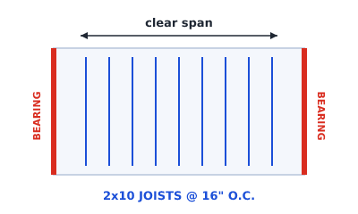 Joist direction and the supports that define each span
The supports are the sill plate on the foundation, girders and bearing walls. Each joist end needs 1-1/2 inches of bearing on wood or metal, or 3 inches on masonry or concrete, unless a joist hanger carries it (R502.6). Joists framing from opposite sides over a bearing support lap not less than 3 inches and are nailed with at least three 10d face nails (R502.6.1). Joists framing into the side of a wood girder sit on approved framing anchors or ledger strips not less than nominal 2 by 2 inches (R502.6.2).
Two layout rules catch people out. Joists under a parallel bearing partition must be sized for the load, and double joists separated for piping need full-depth solid blocking at not more than 4 feet on center (R502.4). Bearing partitions perpendicular to the joists cannot be offset from the support below by more than the joist depth unless the joists are sized for it. Floor openings are framed with header and trimmer joists: a header up to 4 feet is a single member the same size as the joist, and over 4 feet the headers and trimmers are doubled (R502.10).
Span limits are in the guides linked in the table. The cap on the floor is the subfloor, covered by Section R503.
What does an exterior wall framing diagram show?
An exterior wall framing diagram shows a bottom plate, studs at a stated spacing, a double top plate, and a header, jack studs and king studs at each opening.
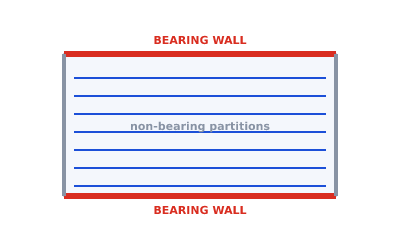 Bearing walls in red at the ends of the joist run; partitions in gray
The rules sit in Section R602.3. Studs must be continuous from support at the sole plate to support at the top plate, with the support being a foundation, a floor, or a ceiling or roof diaphragm. Studs have full bearing on a nominal 2-by plate at least as wide as the studs (R602.3.4). The double top plate overlaps at corners and at intersections with bearing partitions (R602.3.2).
Stud size, height and spacing come from Table R602.3(5), where bearing studs are listed at a laterally unsupported height of 10 feet. Headers are supported by jack studs or approved framing anchors, with the number of full-height studs set by Table R602.7.5 (R602.7.5). Concealed stud cavities need fireblocking vertically at the ceiling and floor levels and horizontally at intervals not exceeding 10 feet (R602.8, R302.11). Names for every piece are in the guides linked in the table above.
How is a 2 story house framed?
A 2 story house is framed as two stacked floor-and-wall assemblies: the second-floor deck sits on the first-story top plates, and the upper walls stand on that deck.
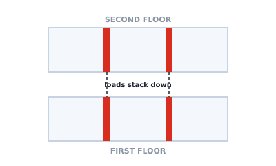 Bearing walls stacking from one story to the next
Bearing walls should stack so the load follows a direct line to the foundation. The first-story walls carry the second floor plus the roof, so they are the most heavily loaded. Table R602.3(5) shows the effect: a 2x4 bearing stud is not listed for two floors plus a roof-ceiling assembly, a 2x4 carrying one floor plus a roof may be 16 inches on center, and a 2x6 carrying two floors plus a roof may be 16 inches on center. The upper-story walls, carrying roof only, may be 24 inches on center in either size.
Joists bearing on the first-floor top plates follow the same bearing rules as any other floor (R502.6). The two-story floor plan arrangement, and how to draw it, are in floor framing plan for a two-story home. Wall bracing (R602.10) is a separate check.
What does the roof part of the diagram show?
The roof part shows ceiling joists tying the walls together, rafters rising to a ridge, collar ties, and roof sheathing on top. Section R802.2 requires the roof and ceiling assembly to provide continuous ties across the structure so roof thrust is not applied to the walls.
- Ceiling joists are continuous across the structure or securely joined over interior partitions, with ends lapped not less than 3 inches or butted over bearing partitions and toenailed (R802.5, R802.5.2.1).
- Rafters are framed opposite each other to a ridge board and not offset more than 1-1/2 inches (R802.4.2). A ridge board is not less than 1 inch nominal and not less in depth than the cut end of the rafter (R802.3).
- Collar ties are at least 1 by 4 inches nominal, not more than 4 feet on center, in the upper third of the attic space (R802.4.6).
- Bearing on the wall is not less than 1-1/2 inches on wood or metal (R802.6).
- Trusses replace rafters and ceiling joists as an engineered system, designed under Section R802.10 with truss design drawings.
Uplift connections from roof to wall are covered in Section R802.11. Where no ceiling joists or rafter ties provide the tie, Section R802.3 requires a ridge beam designed by accepted engineering practice.
How do you read a house framing diagram?
Read it from the roof down, following the load: rafters, then the bearing walls they land on, then the joist direction beneath each wall, then the stud callout, headers, and finally the sill plate and foundation.
What this article does not cover
Roof sheathing, wall sheathing and subfloor panel thicknesses, wall bracing, uplift connectors, energy code insulation and engineered products are separate topics. The tables and sections quoted are prescriptive limits for their stated conditions only.
Summary
A house frame is a stack: footing and foundation wall, sill plate, floor framing, stud walls, ceiling joists and roof framing, each governed by a different part of the 2021 IRC. Bearing walls stack in line, joists need defined bearing, and walls carrying more floors need larger studs or closer spacing under Table R602.3(5). Check the adopted code edition and local amendments for your site.
Draw the framing layers
Framing Plan is a preliminary drawing aid for floor and roof framing layouts: it draws joist layouts, beams and openings and exports PNG, PDF and DXF. Its sample span profile uses demo figures and the editor works in millimetres, so it does not check code spans. Open the framing studio to sketch the floor over your wall lines, then have the layout verified for your project.