Framing Plan generates a preliminary joist field with a deterministic geometry pipeline: take the bay polygon, choose a span axis, distribute lines at the selected on-center spacing, clip each line to the polygon, deduct assumed end bearing, and compare the resulting clear span with the active profile. It is useful for drawing and coordination. It is not structural analysis.
This article documents the current implementation so you can understand what the app did, reproduce its logic, and recognize what it did not check.
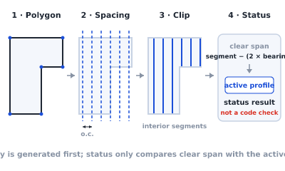 Joist generation pipeline from polygon to profile status
Inputs to the generator
The joist generator receives three main inputs:
- A bay: a closed polygon in millimeters plus a user-selected span angle.
- An engineering profile: member names and depths, allowed spacings, a span lookup table, and an assumed bearing length.
- An optional spacing override. If none is supplied, the generator uses the smallest spacing listed in the profile.
The polygon utilities support simple convex and concave outlines, including L-shaped bays. They do not support self-intersecting polygons. The function does not mutate its inputs, and the same inputs produce the same output.
1. Suggest a direction from the bounding box
When you use the automatic direction, the app measures the axis-aligned bounding box of the polygon. If the box is at least as wide as it is tall, the suggestion runs joists vertically; otherwise it runs them horizontally. In both cases, the suggested run follows the shorter bounding-box dimension.
That is intentionally a simple heuristic. It does not examine foundations, beams, walls on other levels, floor openings, services, loads, material availability, or connection details. A rotated or irregular shape may also have a more efficient direction than the two axis-aligned choices. The user can override the suggestion.
2. Set the on-center layout positions
The selected span angle becomes a span axis. The engine calculates a perpendicular axis and projects the polygon onto it to find the full distribution width.
Starting at one projected edge, it adds layout positions at the chosen on-center spacing. It also adds a joist at the far edge. This produces an edge joist at each end plus the repeated field between them. If the total width is not an exact multiple of the spacing, the last space at the far edge is narrower than the nominal interval; the engine treats that as an expected edge condition, not an error.
3. Clip each joist line to the polygon
At every layout position, the engine creates an infinite line running along the span axis and intersects it with every polygon edge. It sorts and merges the intersection points, then keeps only segments whose midpoint is inside the bay.
For a rectangular or other convex bay, one line normally produces one joist segment. For a concave bay, the same line can cross the polygon more than once, so it can produce separate interior joist segments with the exterior notch discarded. A tiny perpendicular nudge handles the special case where an edge joist lies exactly on the polygon boundary.
This clipping step is why joists follow an L-shaped outline rather than extending through the missing corner.
4. Calculate member length and clear span
For each clipped segment, the engine records its geometric length. It then calculates:
clear span = clipped length − (2 × profile bearing length)
The subtraction represents assumed bearing at both ends. Clear span is never allowed to fall below zero. In the bundled sample profile, the assumed bearing length is 40 mm per end, but that number is part of the illustrative profile, not a verified requirement for a real material, support, connection, or jurisdiction.
The generator does not inspect whether a physical wall or beam exists at each segment end, whether it has capacity, or whether the assumed bearing is detailed correctly. Support highlighting elsewhere in the app is also a preliminary assumption; see bearing walls on a framing plan.
5. Look up a member and status
The selector filters the active profile to rows matching the chosen spacing, pairs those rows with the profile's member catalog, and sorts the matches from shallowest to deepest. It then returns:
| Status | What the engine did |
|---|---|
| ok | Found the shallowest listed member whose profile value is at least the calculated clear span |
| over-span | Found matching rows, but none reached the clear span; returned the deepest listed member only as a rendering fallback |
| no-member | Found no usable profile row at that spacing |
An over-span fallback is not a selected adequate member. It keeps the drawing visible while flagging that the active catalog did not contain a matching value.
The critical limitation: the bundled values are fabricated
The web app currently starts with Sample Metric Timber (illustrative). Its source states that the joist and beam span figures are fabricated for development and demos, are not derived from any building code, and must not be used for construction. The sample beam catalog also does not model tributary-load coupling.
That means the live status demonstrates how a future authoritative profile can plug into the engine; it does not make the current sample a span table. A real deployment would need a profile sourced, versioned, and applied for the relevant code, manufacturer, material, load case, service conditions, and jurisdiction. Even then, geometry lookup would not replace checks outside the profile, including concentrated loads, vibration, holes, bearing, connections, stability, fire, durability, and support capacity.
What to do with the generated layout
Use the result to explore direction and spacing, coordinate openings, expose support assumptions, and produce a clean preliminary drawing. If the geometry changes, regenerate and review the affected annotations and levels. Before construction use, replace demo assumptions with project-specific design information and obtain the structural review and approvals required locally.
To try the workflow, follow how to draft a preliminary floor framing plan or experiment with floor joist spacing in the framing studio.