A flat roof framing plan, more accurately called a low-slope roof framing plan, shows the chosen roof structure, its supports and openings, and the slope or drainage information that must coordinate with it. When the system uses joists supporting a deck, its plan-view geometry can resemble a floor framing plan. That similarity is useful for preliminary layout, but it does not apply to every low-slope roof system.
For the wider roof picture (pitched roofs, rafters, trusses), see the roof framing plan guide.
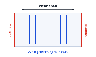 A flat roof framed with joists spanning onto bearing walls, like a floor
When the layout resembles a floor
A low-slope wood roof may use repeated joists between walls or beams with a roof deck above, commonly 2x8 through 2x12 at 16" or 24" on center. In that case, the plan needs joist direction and spacing, support lines, beams, and framing around openings, the same categories used for a floor. Other low-slope roofs use different materials or member systems, so first identify the actual structural concept rather than choosing it from slope alone.
What's different from a floor
Three things set a flat roof apart:
- Design loads. Roof design can include dead load, wind uplift, snow or rain where applicable, maintenance access, equipment, solar arrays, and ponding effects. The project location and roof assembly matter.
- Slope and drainage. The roof needs positive drainage appropriate to its covering and local requirements. Slope may come from sloped structure, tapered insulation, sloped fill, or another designed assembly, so the framing direction and the drainage slope direction are not necessarily the same.
- Openings and rooftop items. Skylights, hatches, drains, ducts, and equipment may create structural and roofing coordination zones.
Laying out a flat roof framing plan
- Footprint: set the roof outline.
- Structural system: record whether the concept uses joists or another system; do not infer it from the roof being low-slope.
- Direction and spacing: if using joists, compare directions against support, openings, drainage, and rooftop loads. (See floor joist spacing.)
- Support assumptions: mark the walls and beams intended to receive reactions, and trace support below. (See load-bearing walls.)
- Openings and equipment zones: coordinate skylights, hatches, penetrations, drains, and equipment; flag final framing and curb details for design.
- Annotate drainage: show slope arrows, high and low points, primary drains, and any required overflow drains or scuppers on the appropriate roof drawings.
- Export: PDF for review, or DXF for CAD.
For a joisted concept, the geometry steps in how to draft a preliminary floor framing plan are reusable. Roof loads, slope, drainage, roofing and flashing interfaces, and wind restraint remain additional project-specific work.
Using Framing Plan for a flat roof
If the preliminary concept uses joists, Framing Plan can draw the footprint, joist field, support assumptions, beams, and openings. Add the slope and drainage information as annotations for coordination. The app does not calculate roof drainage, ponding, wind uplift, snow load, member capacity, or roofing membrane and flashing design.
Keep it preliminary
Roof structure and drainage require project-specific design. As one code example, not a universal prescription, the 2024 International Residential Code requires roof drainage at low points and secondary drainage in specified conditions. Roof and ceiling framing sits in IRC Chapter 8. Use the edition, amendments, and rules adopted for the actual location, roof covering, and project. The app output remains a preliminary layout aid.
Try it
Lay out a flat roof in your browser the same way you'd frame a floor. Open the framing studio to start, or read the full roof framing plan guide.